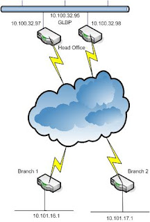
First, Let explain about network diagram, HQ has two internet connections. Each Branches has one internet connection. HQ is using GLBP loadbalancing protocol. All Branches and HQ are running by RIP protocol over GRE Tunnel interface.
HQ1 Router--> 1st, set the ip address for LAN and WAN
interface FastEthernet0/0
description ** WAN interface **
bandwidth 10000
ip address 172.16.97.218 255.255.255.252
speed 100
full-duplex
interface FastEthernet0/1
description ** LAN Segment **
ip address 10.100.32.97 255.255.252.0
duplex auto
speed auto
2nd-->Create site to site GRE Tunnel for Branch 1 & 2
interface Tunnel101
description ** (GRE for Branch1) **
bandwidth 512
ip address 10.101.255.1 255.255.255.252
ip rip advertise 10
tunnel source 172.16.97.218
tunnel destination 10.232.12.74
!
interface Tunnel102
description ** (GRE for Branch 2) **
bandwidth 512
ip address 10.101.255.9 255.255.255.252
ip rip advertise 10
tunnel source 172.16.97.218
tunnel destination 10.232.12.50
3rd--> Static Route for Branches
ip route 10.232.12.72 255.255.255.252 172.16.97.217 name branch1
ip route 10.232.12.50 255.255.255.252 172.16.97.217 name branch2
4th--> Create RIP
router rip
version 2
timers basic 10 60 60 80
passive-interface FastEthernet0/0
passive-interface FastEthernet0/1
network 10.0.0.0
no auto-summary
5th--> Create GLBP
From router config mode:
track 1 interface fastethernet 0/0 ip routing
From LAN interface mode:
glbp 5 ip 10.100.32.95
glbp 5 preempt
glbp 5 weighting 110 lower 95 upper 105
glbp 5 weighting track 1 decrement 20
Do the same steps in HQ2 Router
HQ2 Router-->
track 1 interface fastethernet 0/0 ip routing
interface FastEthernet0/0
description ** WAN interface **
bandwidth 10000
ip address 172.17.97.218 255.255.255.252
speed 100
full-duplex
interface FastEthernet0/1
description ** LAN Segment **
ip address 10.100.32.98 255.255.252.0
duplex auto
speed auto
glbp 5 ip 10.100.32.95
glbp 5 preempt
glbp 5 weighting 110 lower 95 upper 105
glbp 5 weighting track 1 decrement 20
interface Tunnel201
description ** (GRE for Branch1) **
bandwidth 512
ip address 10.101.251.1 255.255.255.252
ip rip advertise 10
tunnel source 172.17.97.218
tunnel destination 10.232.12.74
!
interface Tunnel202
description ** (GRE for Branch 2) **
bandwidth 512
ip address 10.101.251.9 255.255.255.252
ip rip advertise 10
tunnel source 172.17.97.218
tunnel destination 10.232.12.50
router rip
version 2
timers basic 10 60 60 80
passive-interface FastEthernet0/0
passive-interface FastEthernet0/1
network 10.0.0.0
no auto-summary
ip route 10.232.12.72 255.255.255.252 172.17.97.217 name branch1
ip route 10.232.12.50 255.255.255.252 172.17.97.217 name branch2
Branch1 Router-->1st, set the ip addresses for LAN and WAN
(in this example atm0.1 is using for WAN interface)
interface ATM0
no ip address
no ip route-cache cef
no ip route-cache
no atm ilmi-keepalive
dsl operating-mode auto
!
interface ATM0.1 point-to-point
description ** (ATM/ADSL Wan Interface) **
ip address 10.232.12.74 255.255.255.252
no ip route-cache
pvc 8/35
protocol ip 10.232.12.73
interface Ethernet0
description Connecting to internal Lan
ip address 10.101.16.1 255.255.255.224
ip rip advertise 10
ip policy route-map clear-df
hold-queue 100 out
access-list 101 permit tcp 10.101.0.0 0.0.255.255 any
route-map clear-df permit 10
match ip address 101
set ip df 0
Why we add route-map statement? see ref:
http://www.cisco.com/en/US/tech/tk827/tk369/technologies_tech_note09186a0080093f1f.shtml
interface Tunnel101
description ** (GRE to HQ1) **
bandwidth 512
ip address
ip rip advertise 10
ip tcp adjust-mss 1436
tunnel source ATM0.1
tunnel destination 172.16.97.218
!
interface Tunnel201
description ** (GRE to HQ2) **
bandwidth 512
ip address
ip rip advertise 10
ip tcp adjust-mss 1436
tunnel source ATM0.1
tunnel destination 172.17.97.218
router rip
version 2
timers basic 10 60 60 80
network 10.0.0.0
no auto-summary
!
ip classless
ip route 172.16.97.216 255.255.255.252 ATM0.1
ip route 172.17.97.216 255.255.255.252 ATM0.1
Do the same steps for Branch2 Router;
no ip address
no ip route-cache cef
no ip route-cache
no atm ilmi-keepalive
dsl operating-mode auto
!
interface ATM0.1 point-to-point
description ** (ATM/ADSL Wan Interface) **
ip address 10.232.12.50 255.255.255.252
no ip route-cache
pvc 8/35
protocol ip 10.232.12.49
interface Ethernet0
description Connecting to internal Lan
ip address 10.101.17.1 255.255.255.224
ip rip advertise 10
ip policy route-map clear-df
hold-queue 100 out
access-list 101 permit tcp 10.101.0.0 0.0.255.255 any
route-map clear-df permit 10
match ip address 101
set ip df 0
Why we add route-map statement? see ref:
http://www.cisco.com/en/US/tech/tk827/tk369/technologies_tech_note09186a0080093f1f.shtml
interface Tunnel102
description ** (GRE to HQ1) **
bandwidth 512
ip address 10.101.255.2
ip rip advertise 10
ip tcp adjust-mss 1436
tunnel source ATM0.1
tunnel destination 172.16.97.218
!
interface Tunnel202
description ** (GRE to HQ2) **
bandwidth 512
ip address
ip rip advertise 10
ip tcp adjust-mss 1436
tunnel source ATM0.1
tunnel destination 172.17.97.218
router rip
version 2
timers basic 10 60 60 80
network 10.0.0.0
no auto-summary
!
ip classless
ip route 172.16.97.216 255.255.255.252 ATM0.1
ip route 172.17.97.216 255.255.255.252 ATM0.1
No comments:
Post a Comment