A common connection point for devices in a network. Hubs are commonly used to connect segments of a LAN. A hub contains multiple ports. When a packet arrives at one port, it is copied to the other ports so that all segments of the LAN can see all packets.
Switch
In networks, a device that filters and forwards packets between LAN segments. Switches operate at the data link layer (layer 2) and sometimes the network layer (layer 3) of the OSI Reference Model and therefore support any packet protocol. LANs that use switches to join segments are called switched LANs or, in the case of Ethernet networks, switched Ethernet LANs.
Router
A device that forwards data packets along networks. A router is connected to at least two networks, commonly two LANs or WANs or a LAN and its ISP.s network. Routers are located at gateways, the places where two or more networks connect. Routers use headers and forwarding tables to determine the best path for forwarding the packets, and they use protocols such as ICMP to communicate with each other and configure the best route between any two hosts.
=====================================================
- IP routing traffic should be marked to DSCP CS6; this is default behavior on Cisco IOS platforms.
- HSRP runs on UDP port 1985.
- destination address of HSRP hello packets is the all routers multicast address (224.0.0.2)
- source address is the primary IP address of the router assigned to the interface.
- LDP and tLDP discovery runs on UDP port 646 and the session is built on TCP port 646. During the discovery phase hello packets are sent on UDP port 646 to the 'all routers on this subnet' group multicast address (224.0.0.2).
======================================================
IP SLA control protocol disabled
IP SLAs uses the control protocol to notify the IP SLAs Responder to enable the target port temporarily. This action allows the Responder to reply to the TCP Connect operation. In this example, because the target is not a router and a well-known TCP port is used, there is no need to send the control message.
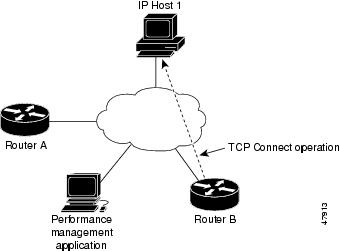
TCP Connect operation as shown in Figure from Router B to the Telnet port (TCP port 23) of IP Host 1 (IP address 10.0.0.1).
======================================================
IP Source Guard
IPSG is a security feature that restricts IP traffic on nonrouted, Layer 2 interfaces by filtering traffic based on the DHCP snooping binding database and on manually configured IP source bindings. You can use IP source guard to prevent traffic attacks if a host tries to use the IP address of its neighbor.
You can enable IP source guard when DHCP snooping is enabled on an untrusted interface.
ip verify source //Source IP Address Filtering
ip verify source port-security //Source IP and MAC Address Filtering
======================================================
EIGRP Passive Interface
- When you configure EIGRP using a broad network statement such as network 10.80.0.0 0.0.255.255; any interface you bring online with an ip address that falls in that range will start advertising and processing received hello’s on that interface.
- In some scenarios you may want to disable EIGRP from sending and receiving Hello’s on a particular interface however you may still need that network which the interface is connected to be advertised throughout the routed domain.
- A great example of this would be disabling EIGRP hello’s on a link that goes from a distribution switch to a layer 2 access switch; another great example would a network hand off link to a 3rd party organization which you have no control over, in this case you would need to advertise that particular link through out your own routed domain but not allow the 3rd party to receive hello’s or send hellos to your device.
- By default RIPv2 will send multicast updates out all interfaces specified within the range of the network command.
- If you configure a static neighbor; not only will that router send updates via unicast to that neighbor out the respected link. It will also send multicast updates out the same link as well. To prevent this from happening, you must utilize a feature called “Passive Interface”
OSPF Passive Interface
- its a feature you enable on a per interface basis which allows a particular interface to participate in a routing process but prevents that interface from forming neighbor relationships by not sending hello packets and discarding received hello packets.
- # Lets say you have a layer 2 access switch and all layer 3 functions of the network occur at the distribution layer. In this case you would not want the router(s) sending hello packets down to the access switch but you’d still want the links participating in a routing protocol to be advertised dynamically. In this case you’d need to use the passive interface feature.
ipv6 address autoconfig default
The default keyword causes a default route to be installed using that default device.
The default keyword can be specified only on one interface.
======================================================The default keyword causes a default route to be installed using that default device.
The default keyword can be specified only on one interface.
IP SLA control protocol disabled
IP SLAs uses the control protocol to notify the IP SLAs Responder to enable the target port temporarily. This action allows the Responder to reply to the TCP Connect operation. In this example, because the target is not a router and a well-known TCP port is used, there is no need to send the control message.
TCP Connect operation as shown in Figure from Router B to the Telnet port (TCP port 23) of IP Host 1 (IP address 10.0.0.1).
======================================================
IP Source Guard
IPSG is a security feature that restricts IP traffic on nonrouted, Layer 2 interfaces by filtering traffic based on the DHCP snooping binding database and on manually configured IP source bindings. You can use IP source guard to prevent traffic attacks if a host tries to use the IP address of its neighbor.
You can enable IP source guard when DHCP snooping is enabled on an untrusted interface.
ip verify source //Source IP Address Filtering
ip verify source port-security //Source IP and MAC Address Filtering
======================================================
BPDU - Bridge Protocol Data Unit are messages exchange between the switches (within redundant LAN).
BPDU frames contain SWITCH ID, originating SWITCH PORT, MAC Address, Switch port PRIORITY, Switch port COST, etc..
Send out as Multicast message (01:80:c2:00:00:00).
3 Types of BPDU are Configuration BPDU (CBPDU), Topology Change Notification (TCN) BPDU, Topology Change Notification Acknowledge (TCA).
# Purpose of BPDU and SPT Algorithm is to AVOID Layer2 Switching LOOPS and BROADCAST STORMS.
================================================================
STP (802.1D) Vs RSTP (802.1W) - STP ports states Listening, Blocking, Disabled (Don't forward Ethernet Frames and don't learn MAC) = Discarding state in RSTP.
In STP, bridge only send out BPDU when they received one on their Root Port. They only Forward BPDU that are GENERATED by Root Bridge.
In RSTP, send out BPDU every hello time, containing current information.
STP includes 2 ports types; STP Root Port and Designated Port.
RSTP includes 2 additional port types; Alternate Port and Backup Ports.
Alternate Port has alternative path to Root Bridge but is currently in a Discarding state. (can be considered as an additional unused Root Port).
Backup Port on a network segment that could be used to reach the Root Bridge, but there is already an Active STP Designated Port for the segment (can be considered as an additional unused Designated Port).
==============================================================
| IEEE 802.1Q | ISL (Inter-Switch Link) |
| Open Standard | Cisco Proprietary |
| Native VLAN is not tagged | Native Vlan is tagged |
| Tags Ethernet Frame | Encapsulate Ethernet Frame |
| Maximum VLANs : 4094 | Maximum VLANs 1000 |
| Header Size : 4 bytes | Header Size : 26 bytes |
==============================================================
When EIGRP returns a stuck in active (SIA) message, it means that it has not received a reply to a query. EIGRP sends a query when a route is lost and another feasible route does not exist in the topology table. The SIA is caused by two sequential events:
- The route reported by the SIA has gone away.
- An EIGRP neighbor (or neighbors) have not replied to the query for that route.
==================================================================
!EIGRP maximum paths - Default to 4 paths for load balancing but maximum that can be set is 16
EIGRP unequal load balancing - variance (n = 1 to 128)
http://sysnetnotes.blogspot.sg/2013/08/eigrp-notes-with-interview-questions.html
==================================================================
Contidions to form EIGRP neighbors
Must receive HELLO PACKET from neighbor router
AS number must be same
Must have identical K-value or Metric
adjacencies will not form unless the primary IP address on connecting interface are on the same subnet
Conditions to form OSPF neighbors
Following parameters within a HELLO PACKET are identical on each router
Area ID
Subnet Mask
Hello Interval
Dead Interval
Authentication
===================================================================
BGP attribute order
- N - Next hop reachability? (If no route to reach Next_Hop, router cannot use this route)
- W - Weight (Bigger value has preference)
- L - LOCAL_PREF (Bigger value has preference)
- L - Locally injected routes (Locally injected routers have preference over iBGP/eBGP)
- A - AS_PATH length (smaller length has preference)
- O - ORIGIN (Prefer I over E, Prefer E over ?)
- M - MED (smaller metric has preference)
- N - Neighbour type (Prefer eBGP over iBGP)
- I - IGP metric to Next_Hop


